Thursday, September 15, 2016

Two steps back, on step forward

It has been more than a year since I wrote about my efforts to create a print for the keypad. Since then I have mostly gone backwards...

I found out that soldering a 0.4mm Quad Flat No-leads package requires good eyes. I did the soldering wrong at first, and probably toasted the chip when testing it - at least it did not work after resoldering it under a microscope. I *knew* that I had two extra chips somewhere - but could not find them.

Thus I decided to go with a ready-made breakout board instead. Etched a new circuit board - and discovered that placing the electrodes behind a 6mm fibre cement board did not work even though I had tested it before doing the first printed circuit board.

New strategy: Create 12 "buttons" from a aluminum rod on a lathe. Use a long time figuring out how to solder leads to the aluminum. Drill holes in fiber board and mount buttons. Decide it looks ugly and scratch the concept.

Finally I gave up and bought a water proof stainless steel matrix keypad from Alibaba.com. It cost me 30 USD for the keypad, 30 USD shipping, and ~15USD in VAT, a total of 75 USD. It is more than I like, but it works! ;-) So now I am back to using a PCF8574 8-bit I/O expander for the keypad.
I have spent so little time on the project lately, that it is hard to remember how far I have come. So tonight I will start a To-do list. Hopefully that will make it a little easier to spend an hour or two on actually working - and not just remembering how far I got the last time.

Thursday, August 20, 2015

Print for touch keypad

At some time I decided to use the Freescale's MPR121 Proximity Capacitive Touch Sensor Controller for the keypad at the entrance.
The chip has 0.4mm pin spacing so I decided not to try isolation milling and because of the print size (about 3x4 inches) it would not be cheap to order a finished print. I could use a breakout board - readily available at eBay for a few dollars - but I got stubborn and decided to etch my own print.
I ordered photo sensitive PCB from Reichelt and found out that I had to illuminate the board for about 25 minutes with the lamp I used. I got stubborn again and started building a UV-LED based PCB lamp. It took to long - and I am not quite done - but today I produced the print I needed. Now I only need to illuminate the board for 40 seconds ;-)
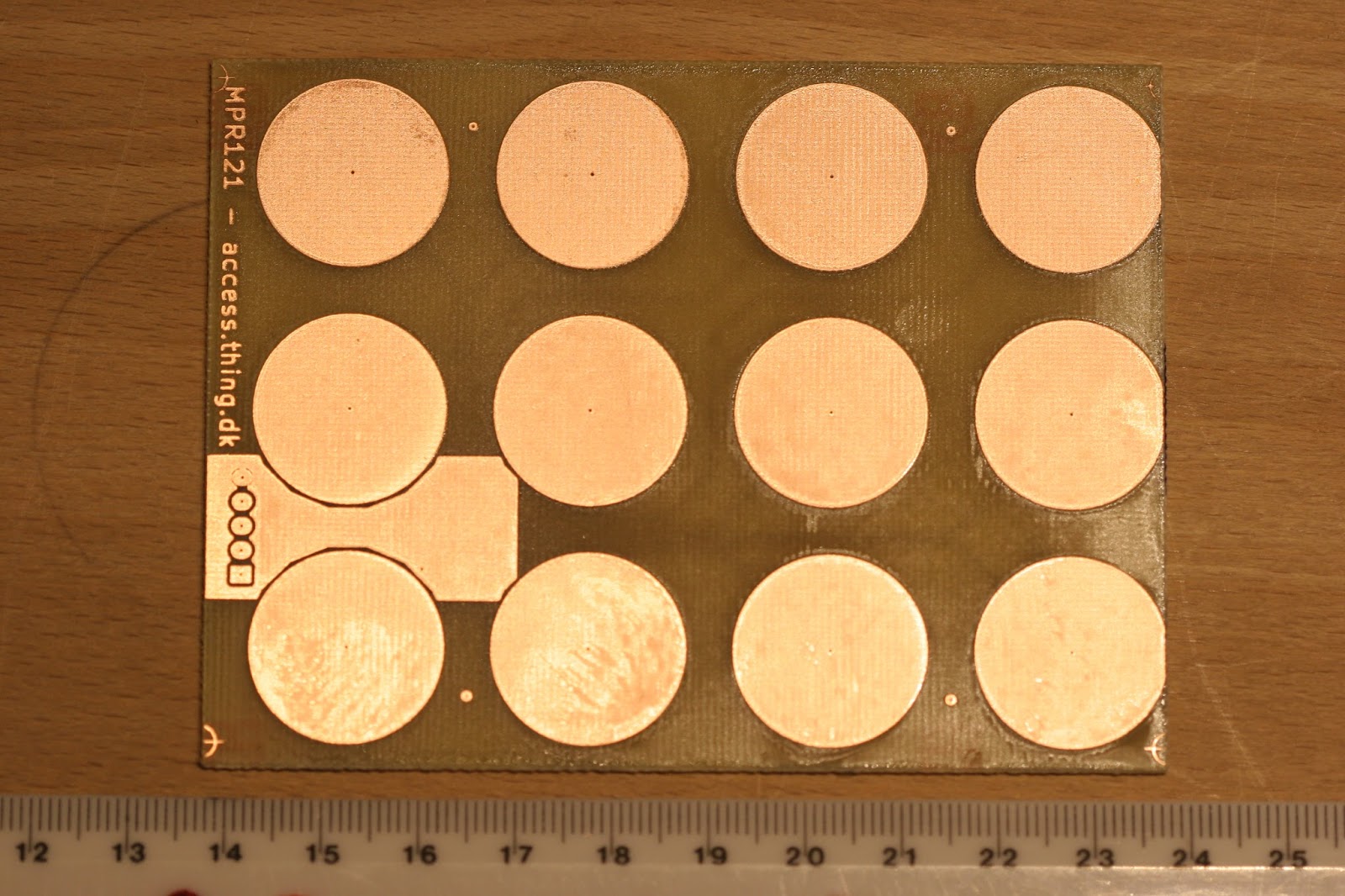
Large pads because it will be placed behind a 6mm board.

Traces from the pads back to the MPR121 chip on the reverse.

Close up of the area where the chip is to be mounted.
Next week I hope to solder the chip and test the board.

Thursday, November 20, 2014

The bigger picture

Tonight I will try to list the hardware components I plan to include in the system, and try to figure out how to connect them all.
  • Input/output devices outside the door, controlled by an Arduino-like microcontroller:
  • Sensors and actuators in the door and door frame, controlled by a Raspberry Pi:
    • Ruko/Abloy EL582 solenoid lock.
      1 output to control the solenoid (through a MOSFET).
      2 inputs for position of bolt and handle.
    • A reed contact and a recessed magnet mounted in door and frame to detect if the door is really closed.
      1 input.
    • A microswitch in back of the strike plate to detect if the dead bolt is in place.
      1 input.
  • Power supply - supplied by 230VAC mains.
    • A 12V 7.2Ah lead acid battery so the access control system can keep running during power failures.
    • A battery charger (230VAC => 12VDC).
    • 12V => 5V and/or 3.3V regulators for the electronics.
    • Perhaps use an analog input to monitor the voltage of the 12V battery.
  • Wild ideas:
    • A PIR-sensor to detect unathorized entry.
    • Monitor my Kibbi-sensors for open windows.
    • A 12V sirene - if unauthorized entry is detected.
      1 output (through a MOSFET).
    • A laser-grid in front of the door - to signal "armed" status ;-)
And now it is late, and the connections must wait for another time. SPI, I²C, serial, RS485 - who knows.


Friday, October 31, 2014

Reboot! Join a hacker space.

How time flies!

It has been a year since my last post. The project has been at a complete standstill while other things happened in my life - like repapering the kids' rooms and restoring the front of a rotting caravan.

All the while I have longed to continue the project but continually failed to actually *do* something. Eventually I decided to join our local hacker space Hal9k. I get around-the-clock access to the facilities, and - more importantly - club night every Thursday. Tonight is the third time I attend - and I love it. The other members are doing all kind of great (and weird) things, and are ready to tell about their projects. I have added a repeating weekly appointment to my calendar, so from now on Thursday night is dedicated to the AccessThing project. Great!

So far I have spent the time remembering where I left the project a year ago, assembling my HDMIPi screen, and finally tonight made an LED blink when connected to the GPIOs of the Raspberry Pi. I really like that the pins can be manipulated by writing to device files under /sys/class/gpio/.
My HDMIPi connected to a breadboard - and my first LED connected to GPIO25.

Two weeks ago I also decided to order another kind of MOSFET. The IRL540N I had bought last summer needs a higher gate-source voltage than 3.3V (from the GPIOs of the Raspberry Pi). So I ordered a roll of 50 low voltage IRL2502 MOSFETs from eBay. When they arrived today I had to pull out my magnifier - they are kind of tiny: 2.9mm x 2.3mm including the legs! Max ratings are 20V Drain-Source and 4.2A (at a higher Gate-Source voltage), so they should easily handle the 12V/220mA I need to drive the Ruko/Abloy EL582 solenoid lock. But it might take a little practice to solder them.
IRL540N and IRL2502.

Sunday, October 20, 2013

Pull request sent

Today I finally finished my rewrite of the MFRC522 library and sent a pull request to the upstream repository: https://github.com/miguelbalboa/rfid/pull/9. Now I look forward to hear Miguel's response - will he welcome my changes or reject them as "too invasive"?
Since last time I also added functions to use the MIFARE Classic Decrement/Increment/Restore/Transfer commands and an example of how to use them (it requires changing the sector trailer).

The next step in the project is building the electronics for driving a Ruko/Abloy EL582 solenoid lock I have bought for use in this project. I expect that to be a lot simpler than rewriting the MFRC522 library ;-)

Wednesday, October 16, 2013

MFRC522 library cleanup

Almost 8 weeks ago I wrote: "I will translate the comments to English, clean up, and implement proper anticollision and support for 7 and 10 byte UIDs."

I have now finished the following subjects:

  • Anticollision
  • 4, 7 and 10 byte UIDs (ie cascade levels 1, 2 and 3)
  • Cleanup
  • Verbose comments in English
  • Tested Authentication and reading from MIFARE Classic cards.
I still need a little work on:
  • Testing writes to MIFARE Classic cards (should not be a problem).
  • Support for reading and writing MIFARE Ultralight cards.
  • Updated example scripts
  • Updated keywords.txt 

So now I actually believe I will finish this job - and hopefully soon so I can get on to building some electronics for the electric lock.

Thursday, August 22, 2013

MIFARE: Initialization and anticollision

Oh my - where did those four weeks go? Well, vacation and getting back to work took most of my time - but I did do a little work on the project.

The Nokia 5110 84x48 pixel display I mentioned last was tested briefly. The code from Adafruit worked just fine - and so did the backlight when I stopped connecting the pin to Vcc and used GND instead. Doh!

The MIFARE reader kit has arrived. It is based on the NXP MFRC522 Contactless Reader IC, and uses SPI for communication with the micro controller. The data sheet for the MFRC522 IC clearly documents how to operate the reader chip, and (I quote) "The digital module manages the complete ISO/IEC 14443 A framing and error detection (parity and CRC) functionality." So far so good. But not a word about the protocol for communicating with the MIFARE chips.
Some time with google.com reveals that the first level of missing information is contained in "ISO/IEC 14443-3 Identification cards -- Contactless integrated circuit cards -- Proximity cards -- Part 3: Initialization and anticollision". It is available for CHF 162 (about USD 175)! Hrmm - more than I like. Luckily the final draft from the WG8 working group is freely available here! Using this protocol I can get the UID of the RFID card. Accessing the card contents is another matter - but never mind, I only need the UID.

I looked around for existing Arduino code to access the reader and cards, and mostly I found variations of the same code:
  • The "original" from Dr. Leong at B2CQSHOP with Chinese comments.
  • A modified version from Grant Gibson.
  • A library version from Miguel Balboa with Spanish comments.
None of these variants support cards with 7 and 10 byte UIDs (the most common is 4 bytes - or at least used to be. MIFARE Ultralight has 7 byte UIDs). Also the code does not support the anticollision protocol, ie it only works if there is only one card in the RF field (I might be wrong on this one, I have not studied the code enough to be certain).

Actually there is another piece of software: NXP has a Visual C++ project available for download (look for "200312"). After a cursory look I have decided to forget about NXP's code, and concentrate on the Arduino code from Miguel Balboa. I will translate the comments to English, clean up, and implement proper anticollision and support for 7 and 10 byte UIDs. All changes will be offered as a GitHub pull request to Miguel, but I do not yet know if he is interested. Stay tuned!