At some time I decided to use the Freescale's
MPR121 Proximity Capacitive Touch Sensor Controller for the keypad at the entrance.
The chip has 0.4mm pin spacing so I decided not to try isolation milling and because of the print size (about 3x4 inches) it would not be cheap to order a finished print. I could use a breakout board - readily available at eBay for a few dollars - but I got stubborn and decided to etch my own print.
I ordered
photo sensitive PCB from Reichelt and found out that I had to illuminate the board for about 25 minutes with the lamp I used. I got stubborn again and started building a UV-LED based PCB lamp. It took to long - and I am not quite done - but today I produced the print I needed. Now I only need to illuminate the board for 40 seconds ;-)
 |
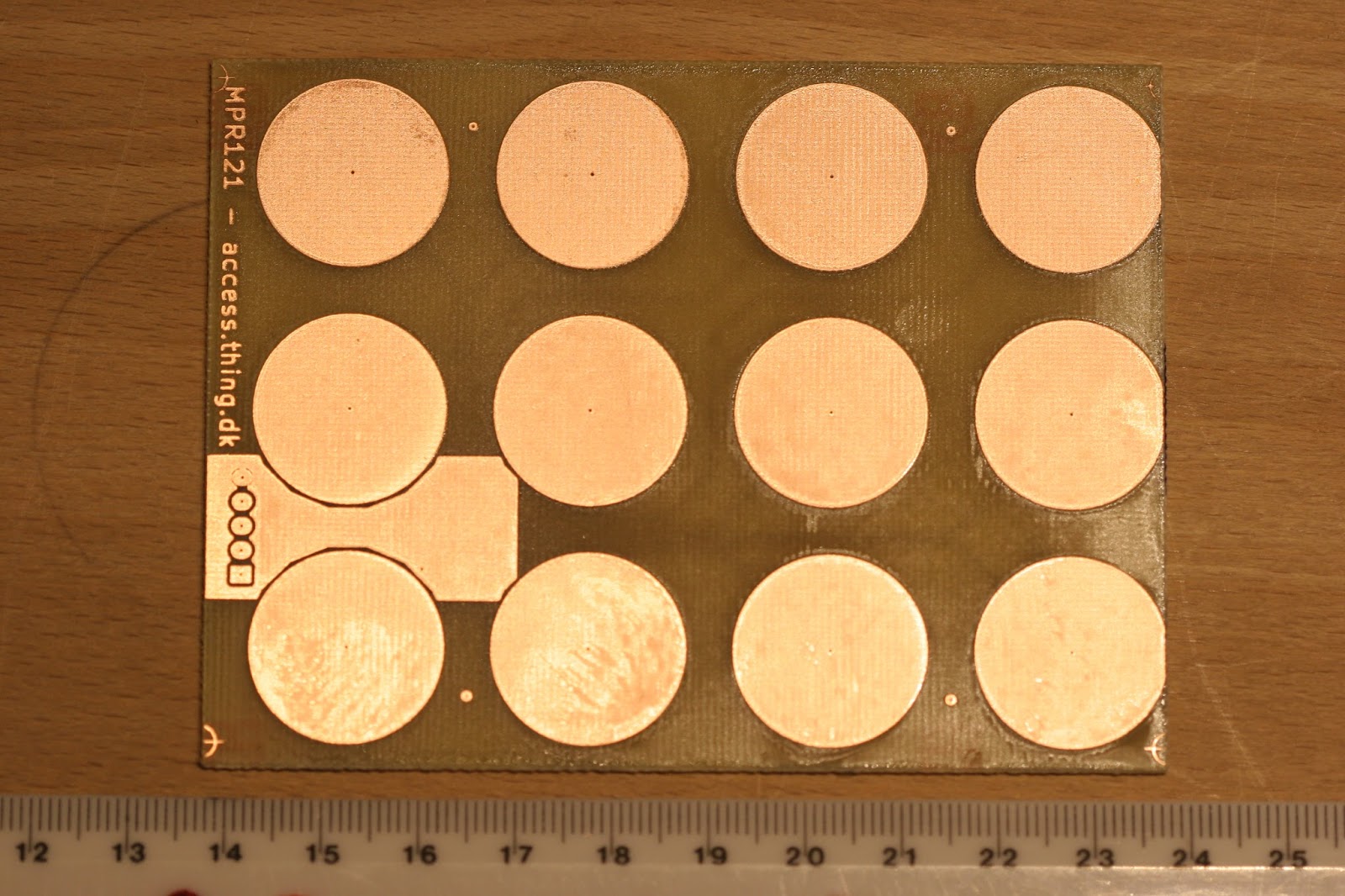
| Large pads because it will be placed behind a 6mm board. |
 |
| Traces from the pads back to the MPR121 chip on the reverse. |
 |
| Close up of the area where the chip is to be mounted. |
Next week I hope to solder the chip and test the board.


No comments:
Post a Comment